گروه الکترونیک فنی حرفه ای و کاردانش هنرستان
آشنایی با دنیای الکترونیک و برقگروه الکترونیک فنی حرفه ای و کاردانش هنرستان
آشنایی با دنیای الکترونیک و برقپیوندها
- نمونه سوالات رشته های فنی حرفه ای و کاردانش نمونه سوالات رشته های فنی حرفه ای و کاردانش
- نـــــــون و القـــــــــــــلم وبلاگ دانش اموزان دبستان
- آموزش برنامه نویسی وبلاگ اموزش برنامه نویسی
- تکنوالکترو
- دانلود نرم افزار و مطالب الکترونیک
- الکترونیک و میکروکنترولر
- پایگاه مجازی برق الکترونیک
- پرشین سیویل
- گوگل
- یاهو
- مبانی و اصول فیبر نوری - مصطفی خسروی
- ازمایشگاه الکترونیک
- رازهای الکترونیک
- انرژی خورشیدی
- مهندسی برق
- گروه الکترونیک هنرستان فنی شهید باقری
- کیت های الکترونیکی
- www.project-esisis.com
- کنکور کاردانی 92 و 93
- کنکور ارشد دانلود سوالات کنکور کارشناسی ارشد
- شارژ سیم کارت خرید شارژ سیم کارت های ایرانسل و همراه اول و رایتل و تالیا
دستهها
- سوالات امتحانی مدارهای الکتریکی 10
- الکترونیک2 28
- مخابرات 19
- ازمایشگاه مخابرات 6
- مشترک 50
- کنکور کاردانی الکترونیک 10
- المپیاد دانش اموزی الکترونیک 5
- پی ال سی (PLC) 5
- آموزش نرم افزار های الکترونیک 7
- دانلود نرم افزار 12
- اموزش چند رسانه ای 10
- اصول اندازه گیری 3
- الکترونیک 1 3
- مبانی برق 9
- مبانی دیجیتال 9
- مدار های الکترونیکی برای ساختن 26
- تازه های تکنولوژی 16
- فایل فلش آموزشی 10
- سوالات امتحان نهایی الکترونیک 6
- سوالات امتحان نهایی الکتروتکنیک 5
- سوال امتحان نهایی مخابرات دریایی 5
- برق صنعتی درجه 2 3
- اتوکد 5
- الکتروتکنیک 11
- فیلم های اموزشی 5
- الکترونیک 8
- مدار فرمان 3
- سوالات امتحانی ماشین DC 4
- سوالات امتحانی ماشین AC 3
- تلویزیون رنگی 4
- برق صنعتی 5
- الکترونیک صنعتی 11
- برق ماشین آلات 1
- کنکور کاردانی الکترونیک و مخابرات دریایی 2
- کنکور کاردانی کامپیوتر 2
- کنکور کاردانی نقشه کشی معماری 2
- امتحانات رشته ساخت و تولید هنرستان 2
- کنکور کاردانی ساختمان 2
- فراگیر ارشد پیام نور 4
- ارشد وزارت بهداشت (پزشکی) 1
ابر برجسب
الکترونیک هنرستان نمونه سوال امتحان الکترونیک ای سی 555 دانلود کنکور الکترونیک هنرستان کنکور الکترونیک هنرستان دانلود پاسخ نامه ارشد فراگیر 92 کنکور ارشد فراگیر 93 دانلود رایگان کنکور الکترونیک امتحان محاسبات فنی ساخت و تولید مدار شوکر الکترونیکی مبانی دیجیتال هنرستان مبانی برق هنرستان امتحان مبانی برق هنرستان امتحان ماشین DC هنرستان امتحان ماشین AC هنرستانبرگهها
جدیدترین یادداشتها
همه- مدار تشخیص زنگ خوردن موبایل
- مداری الکترونیکی که نزدیک شدن دست را تشخیص می دهد
- دانلود سوالات امتحان نهایی رشته های حرفه ای هنرستان شهریور 93
- دانلود سوالات امتحانات نهایی رشته های هنرستان شهریور 93 رشته های فنی
- سوالات کنکور ارشد فراگیر پیام نور 92 و 93 تمامی رشته های فنی مهندسی با پاسخ
- سوالات کنکور کارشناسی ارشد فراگیر پیام نور 92 و 93 تمامی رشته های علوم پایه
- دانلود سوالات کنکور کارشناسی ارشد فراگیر 93 رشته های علوم انسانی
- دانلود سوالات کنکور کارشناسی ارشد وزارت بهداشت سال 93 با پاسخ نامه
- دانلود امتحانات نهایی شهریور 93 هنرستان فنی
- دانلود سوالات امتحان نهایی همه رشته های فنی هنرستان شهریور 93
- دانلود سوالات امتحان نهایی شهریور 93 تمامی رشته های فنی هنرستان
- دانلود کنکور کاردانی رشته الکترونیک 93 فنی حرفه ای
- سوالات کنکور کارشناسی ارشد فراگیر دانشگاه پیام نور 92
- دانلود سوالات کنکور کاردانی به کارشناسی سال 93 سراسری
- دانلود کنکور کاردانی الکترونیک 93
نویسندگان
بایگانی
- اسفند 1393 2
- شهریور 1393 10
- مرداد 1393 4
- تیر 1393 4
- خرداد 1393 5
- اردیبهشت 1393 2
- فروردین 1393 2
- اسفند 1392 8
- بهمن 1392 3
- دی 1392 10
- آذر 1392 20
- آبان 1392 2
- مرداد 1392 10
- خرداد 1392 2
- اردیبهشت 1392 16
- فروردین 1392 36
- اسفند 1391 12
- بهمن 1391 6
- دی 1391 4
- آذر 1391 9
- آبان 1391 1
- مهر 1391 6
- مرداد 1391 1
- خرداد 1391 6
- اردیبهشت 1391 11
- فروردین 1391 12
- اسفند 1390 2
- بهمن 1390 9
- دی 1390 2
- آذر 1390 6
- آبان 1390 4
تقویم
اسفند 1393| ش | ی | د | س | چ | پ | ج |
| 1 | ||||||
| 2 | 3 | 4 | 5 | 6 | 7 | 8 |
| 9 | 10 | 11 | 12 | 13 | 14 | 15 |
| 16 | 17 | 18 | 19 | 20 | 21 | 22 |
| 23 | 24 | 25 | 26 | 27 | 28 | 29 |
جستجو
آمار : 1145245 بازدید
Powered by Blogsky
مدار رله تاخیر زمان فعال شدن
مدار رله تاخیر زمان فعال شدن در شکل زیر مشاهده می شود.
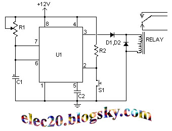
در این مدار با زدن کلید رله خروجی فعال می شود و پس از گذشتن مدت زمان تعیین شده , رله قطع می شود.
توضیحات بیشتر در ادامه مطلب
A time delay relay is a relay that stays on for a certain amount of time once activated. This time delay relay is made up of a simple adjustable timer circuit which controls the actual relay. The time is adjustable from 0 to about 20 seconds with the parts specified. The current capacity of the circuit is only limited by what kind of relay you decide to use.
Parts:
C1__________10uf 16V Electrolytic Capacitor
C2__________0.01uf Ceramic Disc Capacitor
R1__________1 Meg Pot
R2__________10 K 1/4 Watt Resistor
D1,D2_______1N914 Diodes
U1__________555 Timer IC
RELAY______9V Relay
S1__________Normally Open Push Button Switch
MISC_______Board, Wire, Socket For U1
Notes:
1. R1 adjusts the on time.
2. You can use a different capacitor for C1 to change the maximum on time.
3. S1 is used to activate the timing cycle. S1 can be replaced by a NPN transistor so that the circuit may be triggered by a computer, other circuit, etc.
برای نمایش آواتار خود در این وبلاگ در سایت Gravatar.com ثبت نام کنید. (راهنما)


ایمیل شما بعد از ثبت نمایش داده نخواهد شد